Description of wireless Modbus W-Modbus
During reconstructions, but also in new implementations, we may encounter situations where it is necessary to bring a bus with I/O modules or an electricity meter from a remote location into a control cabinet with a PLC. However, it may not be possible to install a traditional cable or optical route. A typical example is a transformer station with a main electricity meter for a facility, which can be several hundred meters away from the main building and not connected to it in any way.
If there is a clear line of sight between the two locations, a wireless link can be used. Nowadays, the license-free 2.4 GHz band (so-called ISM – Industry, Science, Medical) is typically utilized. There are general converters (protocol-independent), as well as special devices that work with specific communication protocols, such as Modbus. These have the advantage that many parameters are pre-configured and optimized for a particular type of serial communication, which significantly simplifies configuration and commissioning. In cases where we need to connect two or more locations with devices using Modbus RTU / RS485 communication, we can use the Kymasgard range of devices from the company S+S Regeltechnik.
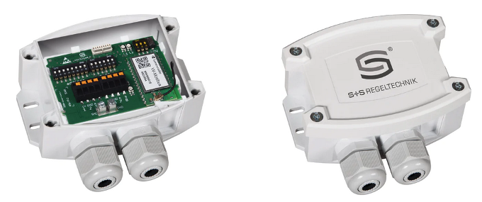
W-Modbus Gateway – Modbus RTU / RS485
The product range includes both sensors for temperature, humidity, and pressure with a wireless Modbus protocol, as well as so-called gateways, which convert a standard Modbus RTU server – such as an electricity meter or photovoltaic inverter – to wireless Modbus. All components use a solution by LumenRadio – OEM modules W-Modbus (for connecting a single Modbus server) and W-Modbus PRO (for connecting up to 16 Modbus servers). These modules are based on MiraOS and MiraMesh standards, which handle wireless transmission at the link layer and include features for device pairing, addressing, and transmission security via 128-bit AES encryption.
If we’re not just dealing with point-to-point communication but a network of multiple wireless devices, it’s important to know that the wireless components use mesh topology – meaning there doesn’t need to be direct line-of-sight between the client and each server. As long as there is a wireless path of no more than 8 “hops” (routes from one device to another) between communicating devices, packets are automatically routed and the entire network acts as one logical unit.
Thanks to frequency hopping, the transmission is highly reliable and resistant to interference, even in industrial environments. The devices have an IP65 rating, so they can be installed outdoors. Signal range is approximately 500 m with direct line-of-sight and 50–70 m inside buildings. However, the material and effective thickness of walls must be considered – for example, if two devices are diagonally below and above each other on different floors, a layer of reinforced concrete several meters thick may block the signal, effectively breaking communication. The more sensors or gateways in the system, the more the mesh technology comes into play, increasing the likelihood that “some” network nodes will always see each other and create a communication path.
For wireless sensors, only the link (Modbus) address is set. The gateway is fully transparent for the Modbus protocol – you only need to set the physical RS485 interface transmission parameters (baud rate, data bits, parity, stop bits) and, if needed, activate the bus termination resistor. On the wireless side, all devices must be logically connected – paired. We’ll use the term “pairing” even when there are more than two devices in the wireless network. Pairing is very simple and requires no additional tools such as converters, computers, or software. Basically, one of the devices is set as the main device (Gateway, Master) and switched to pairing mode. Other devices (Nodes), when also switched to pairing mode, automatically find the gateway and connect to it. This process takes 1–2 minutes. After pairing, the node is locked by flipping a DIP switch, permanently fixing the connection. Device states and pairing progress are indicated by colored LEDs on the devices. After powering up, allow several minutes for network initialization, during which devices search for each other and configure optimal signal paths – Modbus communication will be non-functional during this time.
For advanced settings and diagnostics, the Lumenradio W-Modbus mobile app is available, connecting to the device via Bluetooth. Bluetooth communication is activated by holding the pairing button for three seconds. Once connected, the app allows:
Firmware update of the wireless component
Error detection (duplicate Modbus addresses, communication errors, etc.)
Individual device naming
Network settings inspection
Network configuration documentation as a .pdf file
Example Topology
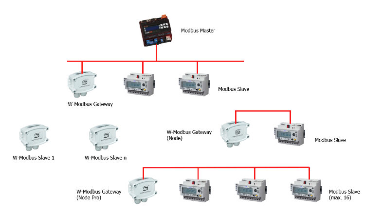
Mixed W-Modbus Topology
Modbus Master: PLC, visualization system, etc. with Modbus RTU / RS485 master function
W-Modbus Gateway: interface between Modbus / RS485 and W-Modbus on the master side
Modbus Slave: electricity meter, thermostat, PV inverter, I/O module, etc. with Modbus RTU / RS485 interface
**W-Modbus Gateway (Node): interface between W-Modbus and RS485 on the slave side, for one slave device**
**W-Modbus Gateway (Node Pro): interface between W-Modbus and RS485 on the slave side, for up to 16 slaves**
**W-Modbus Slave: sensor with a W-Modbus interface, can be integrated directly into the network**
Besides sensors, the product line includes two types of gateways: W-Modbus Gateway and W-Modbus Gateway Pro. Each gateway can be set with a switch to act either as a “gateway” (connected to the RS485 Modbus master) or as a “node,” i.e., an adapter for a Modbus slave device. All devices form one logical Modbus line, and addresses must be unique. W-Modbus Gateway (in Node mode) connects one Modbus slave, while W-Modbus Gateway Pro (in Node mode) can connect up to 16. On the Modbus master side, one W-Modbus Gateway is sufficient, regardless of the number of RS485 slave devices or how many additional Node-mode gateways (or W-Modbus Slave sensors) are in the system.
W-Modbus Slave devices are independent wireless temperature, humidity, or pressure sensors – RS485 connections to them are not possible.
Simplest Topology – Connecting One Remote Modbus RTU Slave:
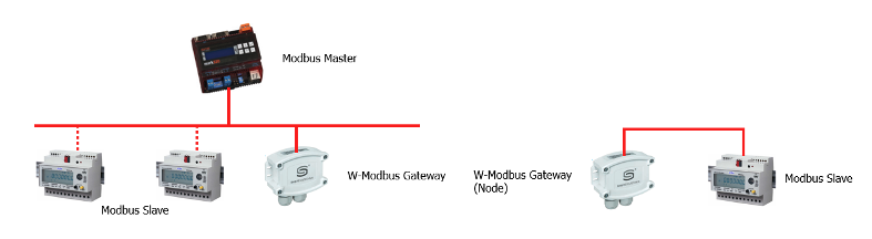
Wireless Connection of one Modbus Slave Device
Only two W-Modbus Gateway devices are needed – one in Node mode.
If there are multiple Modbus slave devices on the remote side, a Gateway Pro must be used:
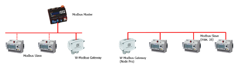
Wireless Connection of a Segment with Up to 16 Modbus Slave Devices
It’s important to consider that inserting a wireless path between RS485 Modbus master and slave introduces a telegram delay of about 60–70 ms. This is clearly shown in the serial communication log – port monitor:
Metallic-only connection – response time 31 ms (based on slave device properties)
11:50:14:142 => 01 03 00 00 00 01 84 0A 11:50:14:173 <= 01 03 02 03 28 B8 AA 11:50:14:690 => 01 03 00 0A 00 01 A4 08 11:50:14:722 <= 01 03 02 0F 28 BD AA
Connection with wireless link (1 hop) – response time 95 ms
11:45:46:340 => 01 03 00 14 00 01 C4 0E 11:45:46:435 <= 01 03 02 09 B9 7F A6 11:45:46:951 => 01 03 00 00 00 01 84 0A 11:45:47:046 <= 01 03 02 03 28 B8 AA
If communication tends to fail or becomes completely non-functional, it will be necessary to set a longer timeout period in the Modbus master's configuration.