Domat IDE
Home
  • Basic description of the Domat IDE
  • Start the IDE
  • Process station, or controller (PLC)
  • Project
  • HMI editor
  • Software
  • Domat devices
Contact
  • Čeština
  • English
Home
  • Basic description of the Domat IDE
  • Start the IDE
  • Process station, or controller (PLC)
  • Project
  • HMI editor
  • Software
  • Domat devices
Contact
  • Čeština
  • English
  • Basic description of the Domat IDE
    • Frequently asked questions
    • Programming options
    • Communication options
    • Hardware capabilities
    • User prerequisities
    • Definitions of terms necessary for work in Merbon IDE
    • General proceedings to program PLCs
  • Start the IDE
    • NewSolution
    • New Solution in Simple mode
    • Hot keys
    • Mouse control
    • Settings
    • Searching variables - Quick Find
    • Project archiving
  • Process station, or controller (PLC)
    • PLC attachment (and platform type settings)
    • Controller runtime update
    • Update from HW device
    • Uploading of program to a PLC
    • Online changes
    • Controller properties
    • Controller configuration
    • PLC Reboot
    • Time setup
    • Firewall settings
    • Dynamic Changes
    • Connection over a Proxy server
    • Alarms log
    • Profiles
    • PLC task definition
    • Communication channel settings
    • Definition of HW variables for a communication channel
    • Automatic assignment of a Domat device
    • Export of devices
    • Import of devices
    • Coupling IOs
    • Global variables mapping to hardware I/O
    • Access to variables of another PLC
    • SSL Communication
    • Modbus server setup
    • BACnet server setup
    • SSCP serial server settings
    • OPC server
    • Variable transformation, configuration of analogue inputs
    • History, saving data in a database
    • Alarm overview
    • Debugging
    • Licensing PLC
    • Break points
    • Break points window
    • Exceptions
    • Manual mode
    • Properties of hardware platforms
    • System status
    • PLC resource usage
    • Variables backup
    • Modbus Configurator
    • Comparison of local and remote project
    • Syslog Protocol
    • Bulk write to variables
  • Communication protocols description

    • BACnet protocol driver
    • Daikin iTC (.NET) protocol driver
    • Hauser (.NET) protocol driver
    • IEC 60870-5-104 protocol driver
    • IEC 62056-21 protocol driver
    • K-Bus protocol driver
    • Modbus protocol driver
    • M-bus protocol driver
    • SoftPLC Link protocol driver
    • SSCP protocol driver
    • Text Parser (.NET) protocol driver
  • Project
    • New project
    • Variable definition
    • Autogen - Automatic mapping of variables
    • FUPLA editor
    • ST editor
    • Watch
    • Variable browser
    • Charts
    • Port Monitor
    • Results
    • Output
  • HMI editor
    • Description of HMI editor
    • Binary function
    • Work in Simple mode
    • Work in Full mode
    • User policy
    • HMI text editor objects
    • Definition of LCD menu for PLC
    • Terminal text menu definition
    • HMI graphical objects
    • Terminal graphic menu definition
    • Creating styles
    • Web server
    • Service web
    • Controller as external webserver
    • Domat Visual
  • Software
    • New Solution
    • New Solution in Simple mode
    • Programming languages
    • Access to inputs/outputs of inner block
    • Initial values
    • Common elements

      • Identifiers
      • Keywords
      • White space
      • Comments
      • Literals
      • Variables
      • Constants
    • Data types

      • Elementary data types (BOOL, INT, REAL, STRING, etc.)
      • Generic data types
      • Derived (user) data types
      • Implicit conversions for elementary types
      • Inference rules for overloaded functions selection
    • Object oriented programming (OOP)
      • Pointer data type
      • Reference data type
      • Namespace
    • Program organisation unit (POU)
      • Functions
      • Standard functions
      • Function blocks
      • Standard function blocks
      • Programs
    • ST language (Structured Text)

      • ST editor
      • ST language commands
      • ST language operators
      • ST drivers
    • FUPLA language (FUnction PLAn)

      • FUPLA editor
      • FUPLA wires
      • Visibility of inputs and outputs at a function block
    • Libraries

      • Creating a new library
      • Creating user library
      • Library prototypes
      • Basic Analogue Boxes

        • Composition / Decomposition

          • Bit Composition (BD18)
          • Bit Composition 8bit (BD18)
          • Bit Decomposition (BD19)
          • Bit Decomposition 8bit (BD19)
          • Int Composition (BD55)
          • Int Decomposition (BD54)
        • Controllers

          • Direct Acting (cooling)

            • On-Off Control - Cooling (B30)
            • P-Controller - Cooling (B32)
            • PI-Controller - Cooling (B34)
            • PID-Controller - Cooling (B36)
          • Reverse Acting (heating)

            • On-Off Control - Heating (B31)
            • P-Controller - Heating (B33)
            • PI-Controller - Heating (B35)
            • PID-Controller - Heating (B37)
          • Helpers

            • Helper: Multi In Bool 8
            • Helper: Multi In Lint
            • Helper: Multi In Real
            • Helper: Multi Out Bool
            • Helper: Multi Out Bool 8
            • Helper: Multi Out Lint
            • Helper: Multi Out Real
        • Mathematics

          • ABS
          • ADD
          • AVG
          • CEIL
          • DIV
          • FLOOR
          • MAX
          • MIN
          • MOD
          • MUL
          • Smart Average (B48)
          • SUB
          • TRUNC
          • TRUNC_TO_LINT
          • Compare Functions

            • EQ
            • GE
            • GT
            • LE
            • LT
            • NE
          • Logarithm / Exponential Functions

            • EXP
            • EXP10
            • EXP2
            • EXPT
            • LN
            • LOG
            • SQRT
          • Specials

            • ISINFINITY
            • ISNAN
            • ISNEGATIVEINFINITY
            • ISPOSITIVEINFINITY
          • Time

            • ADD_DT_TIME
            • ADD_LDT_LTIME
            • ADD_TOD_TIME
            • ADD_LTOD_LTIME
            • CONCAT_DATE_TOD
            • DIVTIME
            • MULTIME
            • SUB_DATE_DATE
            • SUB_DT_DT
            • SUB_DT_TIME
            • SUB_TOD_TIME
            • SUB_TOD_TOD
          • Trigonometric Functions

            • ACOS
            • ACOSH
            • ASIN
            • ASINH
            • ATAN
            • ATANH
            • COS
            • COSH
            • SIN
            • SINH
            • TAN
            • TANH
        • Sources

          • B3 Sine Wave Generator
          • B4 Saw Wave Generator
        • Specials

          • Analogue Incremental Counter (B107)
          • Analogue Memory (B105)
          • Analogue Shift Register (B110)
          • Integer Memory (B106)
          • Integer Shift Register (B111)
          • Integrator (B113)
          • RAND
        • Switches

          • Analogue Demultiplexer (B10)
          • Integer Demultiplexer (B12)
          • MUX
          • SEL
        • Time Blocks

          • GETDELTATIME
          • GETDELTATIME4
          • GETDSTOFFSET
          • GETEVALTIME
          • GETEVALTIME4
          • GETLOCALTIME
          • GETTIMEZONEOFFSET
          • GETUTCTIME
          • PLC Time (B99)
          • Time+Date to Total Seconds (B97)
          • Total Seconds to Time+Date (B98)
          • Conversions

            • COMPOSEDATETIME
            • CONVERTTOLOCALTIME
            • CONVERTTOUTCTIME
            • DATETOTALDAYS
            • DATETOTALHOURS
            • DATETOTALMILLISECONDS
            • DATETOTALMINUTES
            • DATETOTALSECONDS
            • DECOMPOSEDATE
            • DECOMPOSETIME
            • Time Conversion (B100)
            • TIMETOTALDAYS
            • TIMETOTALHOURS
            • TIMETOTALMILLISECONDS
            • TIMETOTALMINUTES
            • TIMETOTALSECONDS
        • Time Dependent

          • Filter (B86)
          • Pulse Width Modulation (B87)
          • Slew Rate Limit (B84)
          • Variable Slew Rate Limit (B85)
        • Transfer Function

          • LIMIT
          • Limits (B82)
          • Linear Interpolation (B83)
          • Two-Point Function (B80)
          • Four-Point Function (B81)
        • Type Casts

          • BCD_TO_UDINT
          • BCD_TO_UINT
          • BCD_TO_ULINT
          • BCD_TO_USINT
          • DT_TO_DATE
          • DATE_TO_LDATE
          • DATE_TO_DT
          • DATE_TO_LDT
          • DATE_TO_LTOD
          • DATE_TO_TOD
          • DT_TO_LDT
          • DT_TO_LTOD
          • DT_TO_TOD
          • LDATE_TO_DATE
          • LDATE_TO_DT
          • LDT_TO_DATE
          • LDT_TO_DT
          • LDT_TO_LDATE
          • LDT_TO_LTOD
          • LTIME_TO_TIME
          • LTOD_TO_DT
          • LTOD_TO_LDT
          • LTOD_TO_TOD
          • TO_BCD_BOOL
          • TIME_TO_LTIME
          • TO_BCD_BYTE
          • TO_BCD_DWORD
          • TO_BCD_LWORD
          • TO_BCD_WORD
          • TO_BYTE
          • TO_DINT
          • TO_DWORD
          • TO_INT
          • TO_LINT
          • TO_LREAL
          • TO_LWORD
          • TO_REAL
          • TO_SINT
          • TO_STRING
          • TO_UDINT
          • TO_ULINT
          • TO_USINT
          • TO_WORD
          • TOD_TO_LTOD
      • Basic Digital Boxes

        • Counters

          • Pulse Counter (BD30)
          • Down

            • Counter DINT (IEC 61131)
            • Counter INT (IEC 61131)
            • Counter LINT (IEC 61131)
            • Counter UDINT (IEC 61131)
            • Counter ULINT (IEC 61131)
          • Up

            • Counter DINT (IEC 61131)
            • Counter INT (IEC 61131)
            • Counter LINT (IEC 61131)
            • Counter UDINT (IEC 61131)
            • Counter ULINT (IEC 61131)
          • UpDown

            • Counter DINT (IEC 61131)
            • Counter INT (IEC 61131)
            • Counter LINT (IEC 61131)
            • Counter UDINT (IEC 61131)
            • Counter ULINT (IEC 61131)
        • Logical Operations

          • AND
          • NEG
          • NOT
          • OR
          • ROL
          • ROR
          • SHL
          • SHR
          • XOR
        • Sources

          • Pulse Generator (BD2)
        • Specials

          • Alarm Memory Ext. (BD57)
          • Boolean Memory (BD51)
          • Falling Edge Detection (IEC 61131)
          • Flip Flop (BD52)
          • Latch Flip Flop (BD53)
          • Multiple Alarm Memory (BD50)
          • Rising Edge Detection (IEC 61131)
          • RS FlipFlop (IEC61131)
          • Single Alarm Memory (BD49)
          • Single Alarm Memory w. Delay (BD56)
          • SR FlipFlop (IEC61131)
          • Toggle
        • Switches

          • Digital Demultiplexer (BD11)
        • Time Dependent

          • Digital Filter (BD15)
          • Monostable FlipFlop
          • Monostable FlipFlop (Non Resetable)
          • Pulse Encoder (IEC 61131)
          • Switch-Off Delay (BD13)
          • Switch-Off Delay (IEC 61131)
          • Switch-On Delay (BD12)
          • Switch-On Delay (IEC 61131)
          • Switch-On/Off Delay (BD14)
        • Type Casts

          • TO_BOOL
      • Basic String Boxes

        • BYTES_TO_STRING
        • CONCAT
        • DELETE
        • INSERT
        • FIND
        • LEFT
        • LEN
        • LINT_TO_STRING
        • LREAL_TO_STRING
        • MID
        • REPLACE
        • RIGHT
        • STRING_TO_BYTES
        • TO_STRING
      • Communications

        • Emails

          • Send Mail
          • Send Mail Triggered
          • Send Mail Custom
        • Input / Output Functions

          • Close Port
          • Get Port Status
          • Open Port
          • Read Port
          • Write Port
        • SMS

          • Receive SMS
          • Send SMS
          • Send SMS Triggered
      • HVAC

        • Boiler Shifts

          • Bit Rotation (T14)
        • Others

          • E-max - Load shedding (T34)
          • Heat / Cool Recovery Block (T39)
          • Heating Curve (T1)
          • Min / Max Controller (T33)
          • Operating Hours (T32)
          • Power Meter (T36)
          • Pump Switch (T35)
          • Average Power Meter (T37)
        • Physics

          • Dew Point (T28)
          • Enthalpy (T29)
          • Solar Calculator (T40)
        • Time Programs

          • Bool Scheduler (T17)
          • Bool Scheduler Basic (T17)
          • Integer Scheduler (T19)
          • Integer Scheduler Basic (T19)
          • Real Scheduler (T18)
          • Real Scheduler Basic (T18)
        • Valve Controls

          • Three Point Control - Feedback (T6)
          • Three Point Control (T2)
          • Three Point P-Controller (T8)
      • System Function

        • Get Exception Error Code
        • Get Startup Flags
        • Mutex Lock
        • Mutex Unlock
        • Resume Normal Tasks
        • Set System Time
        • Stop Interface Entry Point
        • Dynamic Parameters

          • HwConfiguration

            • DateTime Settings
            • Domat DB Parameters
            • Networking
            • Proxy Parameters
            • Restart PLC
            • SSCP Parameters
            • Storage
            • Users Definition
          • Image

            • Alarm

              • GSM
              • SMTP
            • Device

              • BACnet Client Device
              • BACnet Server Device
              • Daikin iTC Device
              • Mbus Device
              • Modbus RTU Device
              • Modbus TCP Device
              • SoftPLC Link Device
              • SSCP TCP Device
            • Channel

              • Serial Channel
              • TCP/UDP Channel
  • Domat devices
    • PLC

      • mark130.2
      • mark220
      • mark220LX
      • mark320
      • mark320LX
      • mark520
      • markMX
      • markMX.2
      • markMX.3
      • markMXL
      • Windows RT
      • ICIO205.2
      • IMIO105.2
      • IMIO110.2
      • w750-8101
      • w750-8102
      • w751-9301
      • wCIO
      • wCIOcom
      • wMX
      • wMXcom
    • Operator units

      • HT102
      • HT104
      • HT200
      • HT3xx
    • Device

      • ECIO2 - Compact I/O module, Ethernet
      • EPC102 - Heating controller
      • FC010 - Communicative fan coil controller
      • FC013 - Communicative room temperature controller for heating and cooling panels and VAV damper
      • FC015 - Communicative room temperature and CO2 controller for heating and cooling panels and VAV damper
      • FC020 - Communicative fancoil controller
      • FCR010 - Communicative fan coil controller
      • FCR011 - Communicative fan coil controller, powered 230 VAC
      • FCR013 - Communicative room temperature controller for heating and cooling panels and VAV damper
      • FCR015 - Communicative room temperature and CO2 controller for heating and cooling panels and VAV damper
      • M090 - Modbus TCP / DALI converter
      • M100 - Temperature sensor
      • M200 - 4 digital outputs
      • M215 - 8 digital outputs with manual intervention
      • M300 - 8 digital (open collector) output module
      • M312, M313 - Triac output module, PWM
      • M315 - 8 SSR outputs, manual intervention
      • M320 - 16 digital outputs module
      • M325 - 16 digital outputs module, manual intervention
      • M400, M401, M410, M411 - Digital input modules
      • M420 - 16 digital inputs module
      • M430 - 32 digital inputs module
      • M500 - 8 analogue inputs module
      • M504 - Analogue input module
      • M560 - Universal analogue input module
      • M580 - String DC current measuring module
      • M610 - Analogue output module
      • M620 - Analogue 4 current loop output module
      • M710 - Pulse counter module, 4 inputs
      • MC102 - Heating controller
      • MCIO2 - Compact I/O module, Ethernet
      • MLIO - Small distributed I/O module
      • MMIO - Small compact I/O module
      • MT020 - Alarm and fault indicator
      • MTala010 - Alarm indicator
      • MW100 - RFID card interface
      • MW240, MW240-B, MW241 - Small I/O module for lights and sunblind control
      • MW501 - Analogue input module
      • MXIO - Compact I/O module
      • R060 - Converter Modbus TCP, RTU/MP-Bus
      • R065 - Converter Modbus TCP/DMX512
      • R091 - Modbus TCP/DALI convertor
      • R220 - 12 digital outputs
      • R312, R313 - Triac output module, PWM
      • R320 - 16 digital outputs module
      • R330 - 32 digital outputs module
      • R420 - 16 digital inputs module
      • R430 - 32 digital inputs module
      • R500 - Universal analogue input module
      • R560 - Universal analogue input module
      • R610 - Analogue outputs module
      • R710 - Pulse counter module, 4 inputs
      • R800 - 8 AI and 8 AO module
      • RCIO - Compact I/O module, Ethernet
      • RMIO - Small compact I/O module
      • RXIO - Compact I/O module
      • Stelix DIP200 - Motion and light sensor
      • UC102 - Communicative heating controller
      • UC120 - Communicative heating controller, output 0..10V
      • UC150 - Communicative heating controller, Ethernet
      • UC200 - Communicative heating and cooling controller
      • UC210 - Communicative heating and cooling controller
      • UC211 - Communicative heating and cooling controller
      • UC220 - Communicative heating and cooling controller, outputs 0...10V
      • UC250 - Communicative heating and cooling controller, Ethernet
      • UC300 - Communicative floor heating controller
      • UI0xx - Room operation unit
      • UI0xxBL Room operation unit with display backlight
      • UI3xx - Room operation unit
      • UI410 - Module for measuring and monitoring
      • UI415 - Solar irradiation integrator
      • UI5xx - Room operation unit, Ethernet
      • UI6xx - Room operation unit, Ethernet, PoE
      • US100 - Communicative heating controller with sunblind control
      • UX0xx - Communicative room units with sunblind control
      • UI9xx Room operation unit with CO2
      • UI9xxBL Room operation unit with CO2 and display backlight
    • Sensors

      • UT090 - Room temperature and CO2 sensor
    • Wago modules

      • w704-2054 - 16× DI or 16× DO
      • w750-404 - 2× up/down counter
      • w750-404-000-005 - 2× 16-bit up counter
      • w750-450 - 4× AI for resistance/temperature measurement
      • w750-451 - 8× AI for resistance/temperature measurement
      • w750-453 - 4× AI for current 0...20 mA
      • w750-455 - 4× AI for current 4...20 mA
      • w750-457 - 4× AI for voltage 10...10V
      • w750-458 - 8× AI for thermocouples
      • w750-459 - 4× AI for voltage 0...10V
      • w750-496 - 8× AI for current 0...20mA, 4...20mA or 3.6...21mA
      • w750-497 - 8× AI for voltage 0...10V DC or ±10V DC
      • w750-511 - PWM signal generator
      • w750-515 - 4× relay module
      • w750-517 - 2-channel relay output
      • w750-530 - 8× DI
      • w750-553 - 4× AO for current 0...20mA
      • w750-555 - 4× AO for current 4...20 mA
      • w750-556 - 2× AO for voltage ±10 V
      • w750-559 - 4× AO for voltage 0...10V
      • w750-597 - 8× AO for voltage 0...10 V and ±10 V
      • w750-600 - bus termination module
      • w750-602 - internal bus power supply module, 10 A
      • w750-613 - internal bus power supply module, 2 A
      • w750-627 - termination module for bus extension
      • w750-628 - bus extension module
      • w750-638 - binary pulse counter
      • w750-642 - EnOcean radio receiver
      • w750-652 - RS-485, RS-422 or RS-232 module
      • w750-960 - PROFIBUS industrial bus connector
      • w750-1400 - 16× DI
      • w750-1405 - 16× DI
      • w750-1406 - 16× DI

MarkMX

Description

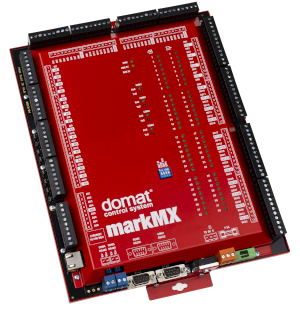
MarkMX is a compact PLC station with a I/O module with I/O mix optimized for HVAC applications. The PLC can be extended by I/O modules over RS485 bus to increase the I/O mix.

Access to inputs / outputs on PLC's internal bus

Communication channel needs to by created to comunicate inputs / outputs on internal BUS of PLC. Channel protocol is Modbus and Link protocol is serial. Inputs / outputs on internal bus can be found as module MXIO on COM3 with address 2.

Inputs

InputST TypeDescription
AI01...AI16realAnalogue inputs.
Settings of transforms for different ranges:
Pt1000 - (analog type R1600, transform: lib.core.v1_0.resistancetotemperature kind: pt1000 pre_k=0,1 pre_q=0, post_k=1, post_q=0 ), the result is in °C, default setting for AI01...AI08
resistance 0-1600 ohm - (transform: lib.core.v1_0.linear k=0,1 q=0 - the inputs provide values 0...16000 = 0...1600 Ω)
resistance 0-5000 ohm - (transform: lib.core.v1_0.linear k=0,1 q=0 - the inputs provide values 0...50000 = 0...5000 Ω) NOTE: the type must be changed to ST:UINT!
Voltage and current is applicable only for inputs AI09...AI16.
current 0-20 mA - (transform: lib.core.v1_0.linear k=0,001 q=0 - the inputs provide values in uA: 0...20 000 = 0...20 mA) The DIP switch must be active at the respective input.
voltage 0-10 V - (transform: lib.core.v1_0.linear k=0,001 q=0 - the inputs provide values in mV: 0...10 000 mV) default setting for AI09...AI16
DI01...DI32boolDigital inputs

Outputs

OutputST TypeDescription
AO1...AO8realAnalogue outputs in %.
0%...0V
100%...10V
DO01...DO32boolDigital outputs

Technical data

Power10 V ÷ 35 V DC, 14 V ÷ 24 V AC (terminals 1,2)
Consumptionmax. 20 VA
ProcessorMPC5200, 400 MHz, 760 MIPS
HW Memory128MB RAM, 64 MB Flash, 128 kB NVRAM FRAM
SW Memory4 MB program, 8 MB RAM, 128 kB NVRAM, 60 kB retain,
256 kB dynamic (OEM) parameters, 1 MB history
Ethernet10/100BaseT, RJ45
COM1, COM2 - RS232300 ... 115 200 bit/s, parity and bits adjustable
COM3, COM4 - RS485 (K+, K-)300 ... 115 200 bit/s, parity and bits adjustable
Max. RS485 bus length
1200m
Analogue inputs
8x Pt 1000, Pt100, Ni1000, resistance 20..1600 Ohm, 20...5000 Ohm
8x 0-10 V DC, Pt 1000, Pt100, Ni1000, resistance 20..1600 Ohm, 20...5000 Ohm, 0(4)...20 mA – configurable via DIP switches and in software
Analogue outputs
8x 0-10 V DC
Analogue outputs load
min. 10 kOhm, max. current 10 mA,
outputs are short-circuit resistant with current limitation to 20 mA
Digital inputs
32x 24V AC/DC – voltage must be applied (no dry contacts)
Input voltage for log. „0“
Input voltage for log. „1“
max. 5 V AC/DC
18 ... 30 V DC, 18... 26V AC @ 7mA
Digital outputs
32x relay, normally open: 5A/250 V AC, 5A/30 V DC, 750 VA, 90 W

Terminals/LED

AI1 to AI8Analogue inputs for resistance measurement only. The range (20...1600 Ohm or 20...5000 Ohm) is configurable over Domat IDE or ModComTool. 
AI9 to AI16Analogue inputs with switchable range - resistance (like AI1 to AI8), - voltage 0...10V, or current 0...20 mA. Analogue input ranges AI9 to AI16 are switched by jumpers for every input separately.
  • resistance, passive temprature sensors - jumper: OFF (default)
  • voltage 0...10 V - jumper: OFF (default)
  • current 0...20 mA - jumper: ON
All analogue inputs AI1 to AI16 have a single common ground, AGND. Inputs are galvanically separated from the rest of the module.
AO1 to AO8Analogue outputs must be loaded by min. 10 kOhm, maximum output current is 10 mA,
outputs are short-circuit resistant with current limitation to 20 mA
DI1 to DI32Digital inputs use external voltage of 24 V AC/DC. Eight inputs on a connector have a common ground.
NO1 to NO32Digital outputs provide 250 V, 5 A, NO relays. A pair of relays has a common terminal COM X, Y.
COM1, COM2Interfaces with CANNON 9 connectors, COM1 and COM2 can be used for a GSM modem to send SMS, for M-Bus coverters, 3rd party integration, etc.
COM3, COM4Serial ports RS485 for I/O modules, room units, room controllers, 3rd party integration etc. Remember that the internal I/Os are connected to COM3, and the COM3 port must be configured as Modbus RTU in order to employ the internal I/Os.
TETechnical Earth, shall be connected to the ground potential (PES, shielding)
Ethernetnetwork
PWROn: markPLC power is OK.
Off: Power not applied, or power source or fuse broken
CONTROLOn: PLC board booted OK.
Off: PLC board booting or board error
RUN I/OFlashes: I/O module OK
Off: I/O module error
COMx RxDFlashes: Data receive on COMx
Off: No data received
COMx TxDFlashes: Data transmit on COMx
Off: No data transmitted
Digital inputs (1..32) – input status (On: active, Off: inactive)
Digital outputs (1..32) – output status (On: active, Off: inactive)

Runtime status indication

LED RUN indicates the runtime status using a sequence of short flashes. The error code persists the power off / on cycle, it is reset only after a project has been uploaded.

Normal state: LED flashes periodically 1 s ON, 1 s OFF – no errors

Error state: LED flashes in a pattern of

  • M short flashes (300 ms ON / 300 ms OFF), where M is the upper code error order
  • 1 s OFF
  • N short flashes (300 ms ON / 300 ms OFF), where N is the lower code error order
  • 2.5 s OFF

Meaning of the error codes:

  • 11 memory low for OS
  • 12 memory low for runtime
  • 13 stack overflow *
  • 21 corrupted / bad RT image
  • 31 HardFault *
  • 4X watchdog of client X expired
  • 51 system file system error
  • 52 web file system error
  • 6X - file system full

* at these errors the PLC stops and the LED starts to flash after power off and on.

Additional info can be found in datasheets at http://domat-int.com/en/downloads/data-sheets.

Prev
mark520
Next
markMX.2