Modbus Configurator
Since version 2.7.0.x
Modbus Configurator description
The Modbus configurator contains several functions that you know from the ModComTool program. These are Address View, Replicate Value, TCP Scanner and Serial Scanner functions. Newly on Modbus it is possible to download the configuration from the module and re-upload any changes.
Address View
Address View is used both for reading individual registers and for writing them. All standard modbus functions (F01, F02, F03, F04, F05, F06, F15, F16) can be used here.
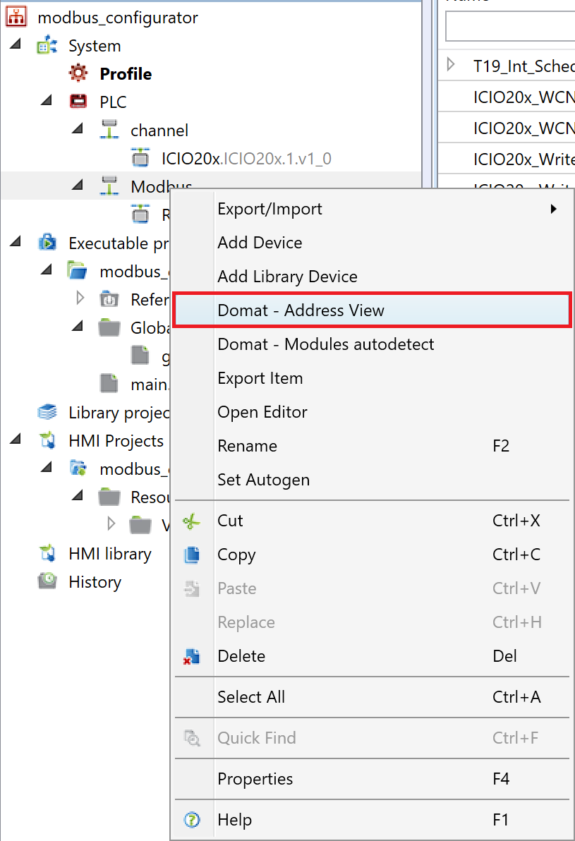
To display the editor, just right-click on the Modbus communication channel and select "Domat - Address View" from the context menu.
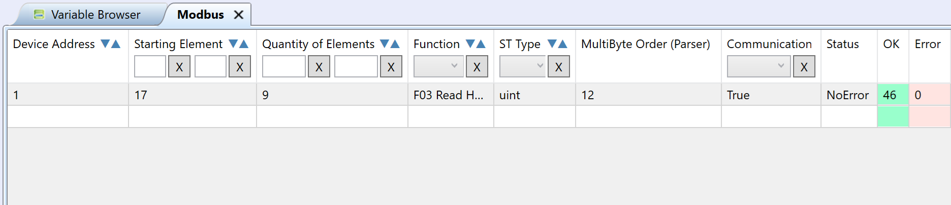
An editor will open, consisting of three windows. In the left window there is an option to set the parameters of the registers to be read. These are the parameters:
- Device Address
- Starting Element
- Quantity of Elements
- Function - F01, F02, F03, F04, F05, F06, F15, F16
- ST Type - basic data types according to the selected function
- MultiByte Order
- Communication - communication enabled
Furthermore, there are only read parameters that detect:
- Status - communication status
- OK - counter of correct packets
- Error - counter of wrong packets
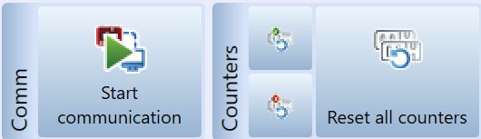
To start communication it is necessary to have the PLC in commissioning mode and then click on "Start communication" in the upper ribbon.
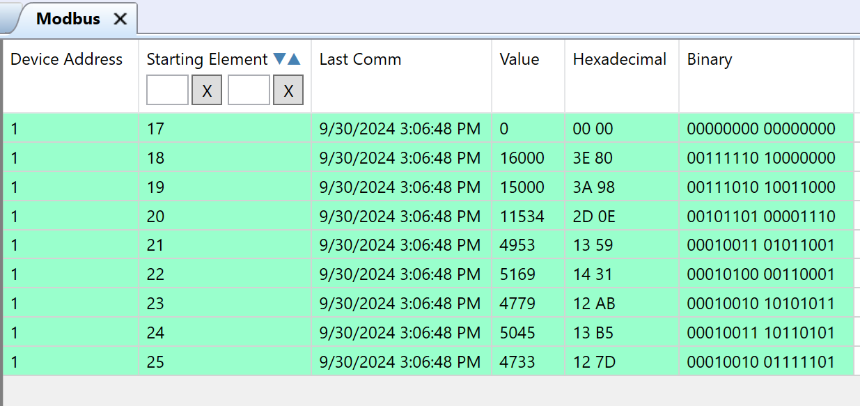
In the right window of the editor, we then see the individual registers that were defined in the left window. Here we see the parameters:
- Device Address
- Starting Element
- Last Comm
- Value
- Hexadecimal
- Binary
- Function - it is not displayed by default setting of data grid
- ST Type - it is not displayed by default setting of data grid
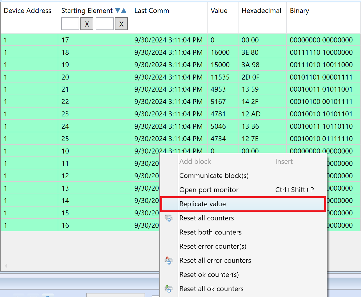
If we use the write function, we can also write to registers in decimal, hexadecimal or binary. Also, the "Replicate Value" function can be used for individual registers.
Replicate Value
Used to write a value to multiple Modbus devices at once.
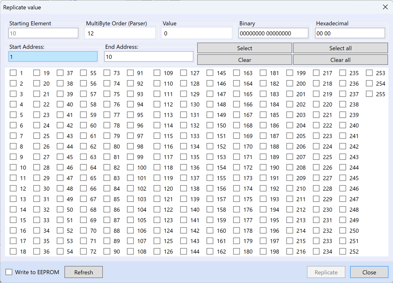
In the dialog for "Replicate Value" there is an starting element that is taken from the set register and cannot be changed. Then we have adjustable MultiByte order parameter and the option to set the value in decimal, binary or hexadecimal form. Below is the option to set the start and end address through which we can mass select the devices to write the value using the "Select" or "Clear" buttons. You can also use the "Select All" or "Clear All" buttons to select or delete all devices from the selection. Of course, it is possible to select devices individually via check boxes via the display of device addresses.
There is also an option to check "Write to EEPROM", where the set value will be preserved even after turning the power off and on. After selecting the device and setting the parameters, we can click the "Replicate" button to write value.
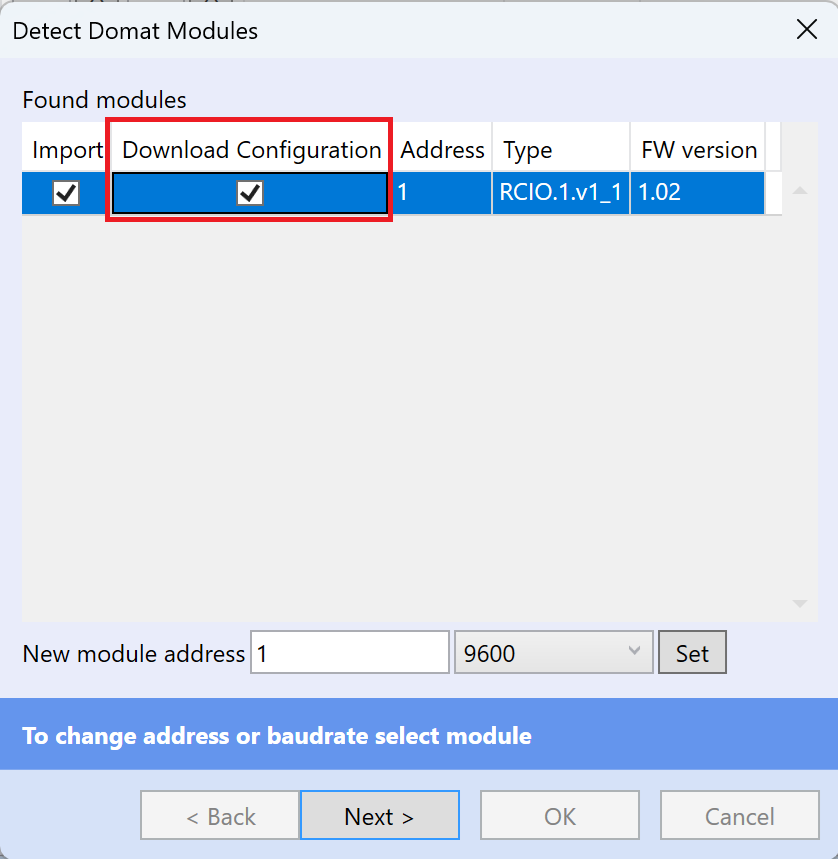
Download Module Configuration
The configuration can be downloaded from the device already during auto-detection of the modules by checking the "Download Configuration" option.
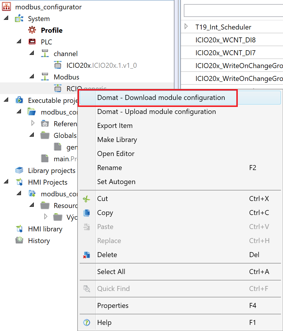
Alternatively, if we add a device from the library, we can right-click on it and select "Domat - Download module configuration".
Upload Module Configuration
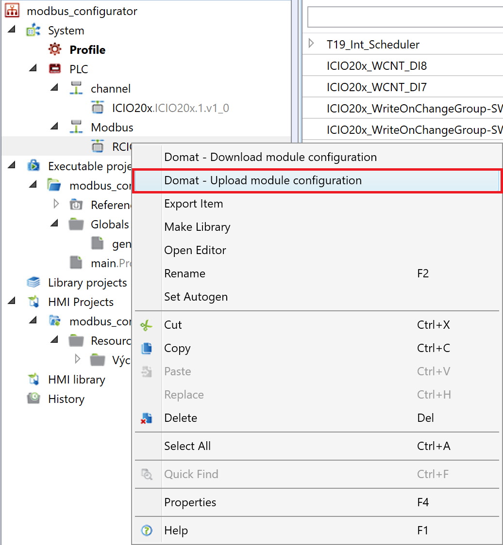
It is the same with uploading the configuration, when after making changes we can upload these changes to the device using "Domat - Upload module configuration".
Modbus TCP Scanner
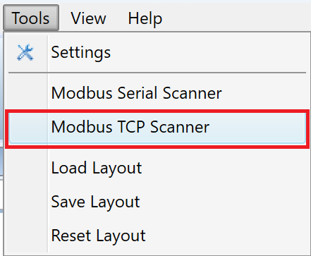
Modbus TCP Scanner can be found in the top bar in the Tools tab.
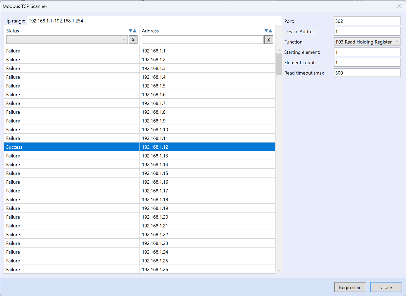
Using this tool we can find Modbus TCP devices in the network. First of all, you need to set the range of IP addresses to be searched. In the next line, we set parameters such as port, device address, function, starting element, element count and read timeout. After pressing the "Begin scan" button, a specific range of IP addresses should be scanned, and the status of the scan can be seen for individual addresses.
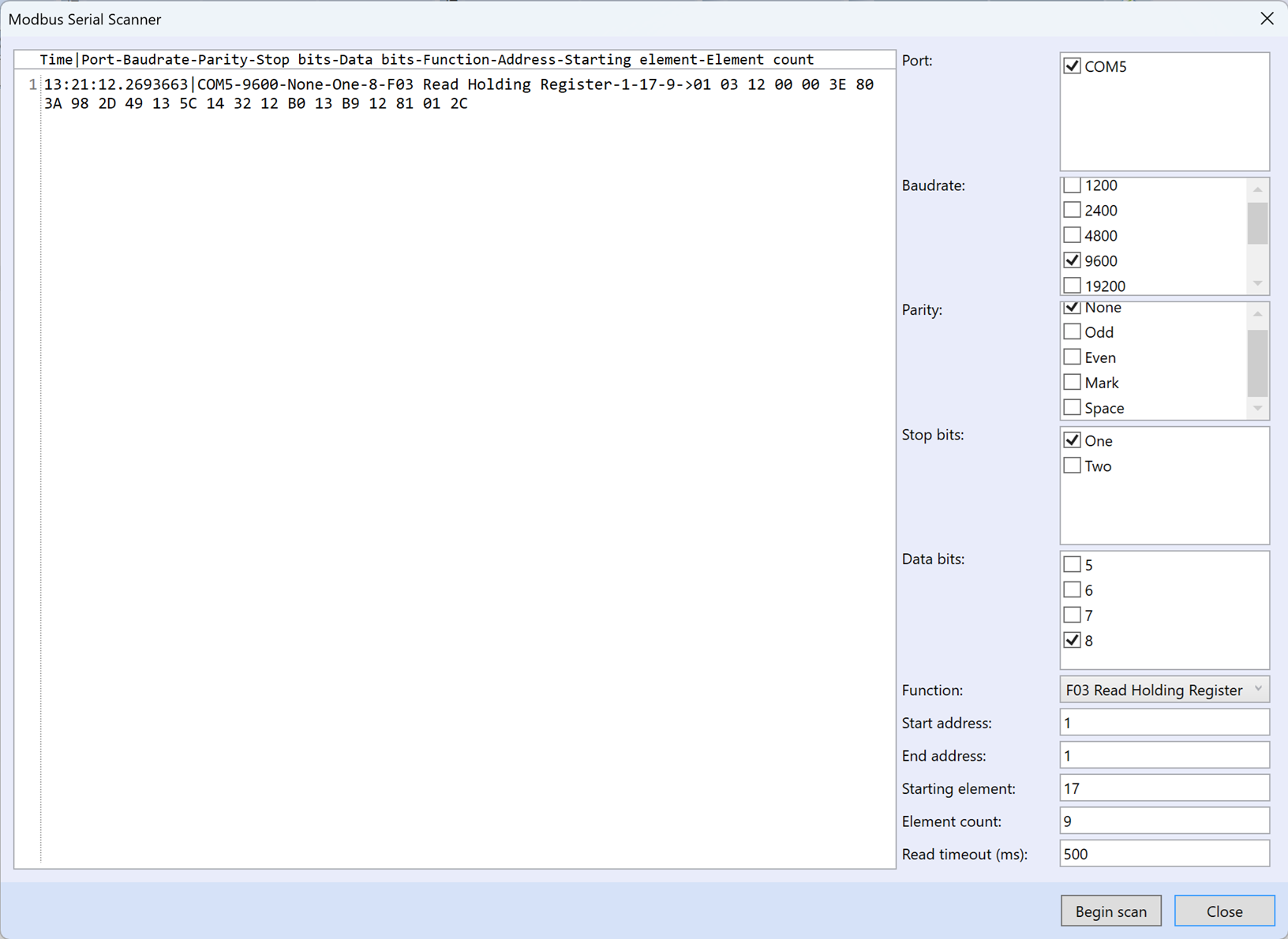
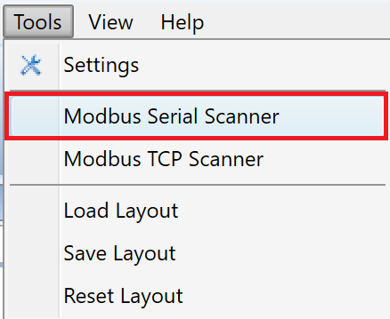
Modbus Serial Scanner
Modbus Serial Scanner can be found in the top bar in the Tools tab.
Using this tool we can find Modbus RTU devices on the serial line.
First, we check the port number, this will be shown to us, for example, after connecting the R080 converter. Then we select baudrate, parity, number of stop bits, number of data bits, function, start address, end address, start element, number of elements, and read timeout.
Finally, we click on the "Begin scan" button, where a basic header with a time stamp and parameters appears, followed by a modbus response.